Used hardware: The same hardware will be used for all experiments for measurement of temperature and humidity:
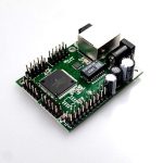
- Numato 8 channel USB GPIO Module;
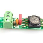
- Connector board for ADC 5V;
- AltonaLab temperature sensor;
- AltonaLab humidity sensor (if is available in the KIT);
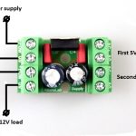
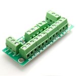
- 5V multi connector power supply board;
- 220V to 12V, 2A power supply;
Click here for the documentation of the used sensors
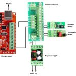
A view of the hardware diagram is shown below (For the Simple educational KIT, humidity sensor is not available):
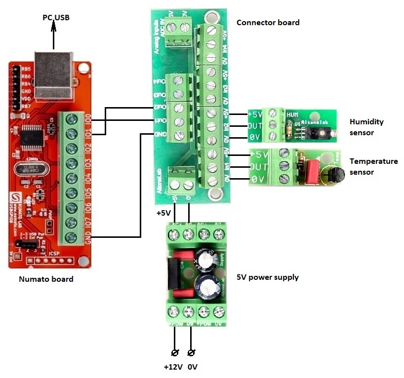
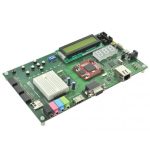
A real image of the connected boards:
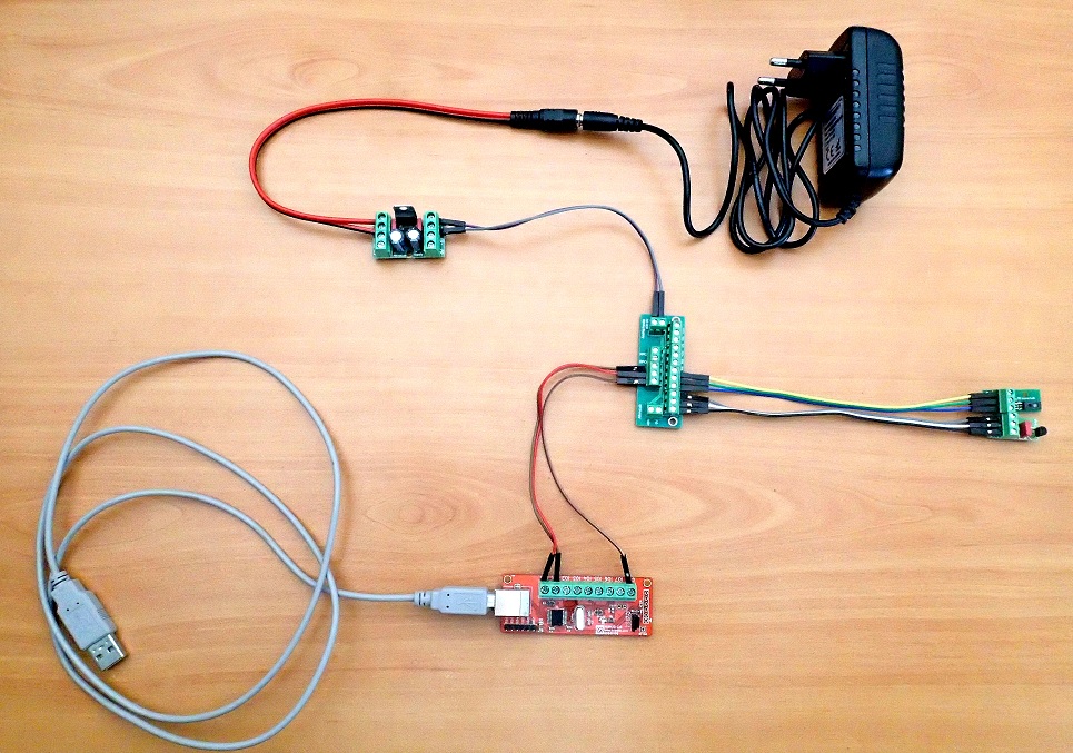
GPIO 0 and GPIO 1 of Numato board are used as analog inputs. Using the Connector board, the Temperature sensor is connected to GPIO 0 and the Humidity sensor is connected to GPIO 1. The both sensors are supplied with 5V power by 5V power supply board, connected to Connector board.
Warning!!! Please be careful, when the hardware diagram is connected, do not touch the boards with each other, because some conducting parts may cause a short circuit!
Experiment: Measure of temperature using expressions.
AltonaLab diagram: KIT_Numato8_USB_GPIO_Temp1.nsm
This experiment is suitable for the KIT, where humidity sensor is not available.
The experiment demonstrates a difficult way to measure temperature, using documentation of sensor and functional block for mathematical expressions and calculating average values. The way is difficult, but demonstrates abilities of AltonaLab software to resolve complicated cases. An easy way to measure of temperature is shown in the next experiment in this article.
Please note: The parameter of Numato functional block CommunicatePerSec is set to 1sec, this means the reading of the value of the sensors is one time per sec. For some other systems, for example if we want to monitoring our home temperature, we can read the sensor’s values one time per 20sec.
Temperature sensor:
The 10bit analog inputs of Numato GPIOs are in voltage range 0..5V. For this range, the corresponding outputs of the Numato functional block on the diagram get values 0..1023. Regarding the documentation, the expression of the temperature conversion is:
T (Celsius) = (Vout-2.7315)*100.0, where Vout is output voltage of the sensor board.
The Analog input value can be converted to a voltage by expression: V=(In*5.0)/1023, where In is raw data read from ADC analog input.
The final conversation to temperature is:
T (Celsius) = (((In*5.0)/1023)-2.7315)*100.0
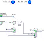
The used diagram in this experiment is shown below:
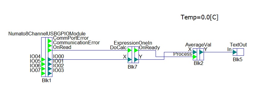
GPIO 0 of Numato board is set as Analog inputs and is presented on the right side of the Numato functional block as Analog output. With double click over the block ExpressionOneIn, is set the expression for temperature conversions. The expression is:
(((X*5.0)/1023)-2.7315)*100.0
Please note, Input parameter from the expressions above, where is explained how to convert ADC value to temperature is replaced with X, because X is name of the input of ExpressionOneIn functional block. The interface with parameters of ExpressionOneIn is shown below:
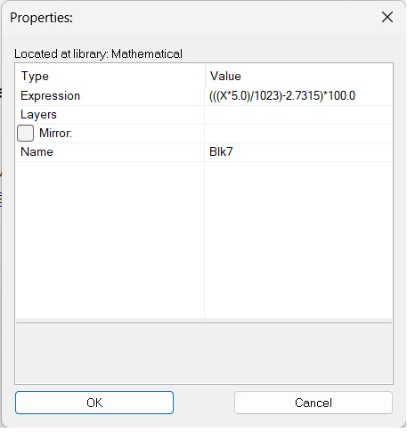
The output OnRead of the Numato block is connected with the input DoCalc of ExpressionOneIn block. This is because, when the Numato block read the data from the analog inputs, its output OnRead becomes for a short time to a high level and this signals the block ExpressionOneIn to start the calculations. When the calculations are done, the output OnReady of the block ExpressionOneIn becomes to a high level and signals the next blocks AverageVal to start theirs calculations too.
The block after ExpressionOneIn is AverageVal. It has a parameter QuequeSize, which determines over how many last measurement to be calculated an average value. If the parameter has a small value, the output of the block will float, if the parameter has a large value, the output will be well filtered, but will be slowly. Please change this value and watch the shown temperature and humidity. Suitable values are between 2 and 30.
The calculated average values are shows using Text controls.
When the diagram is run, to change the temperature, just touch the black sensitive element of the temperature sensor. Because the human temperature is higher, the shown temperature at the running AltonaLab diagram will increase.
Experiment: Measure of temperature and humidity using expressions.
AltonaLab diagram: KIT_Numato8_USB_GPIO_TempHum1.nsm
The experiment demonstrates a difficult way to measure temperature and humidity, using documentation of sensors and functional blocks for mathematical expressions and calculating average values. The way is difficult, but demonstrates abilities of AltonaLab software to resolve complicated cases. An easy way to measure of temperature and humidity is shown in the second experiment in this article.
Please note: The parameter of Numato functional block CommunicatePerSec is set to 1sec, this means the reading of the value of the sensors is one time per sec. For some other systems, for example if we want to monitoring our home temperature, we can read the sensor’s values one time per 20sec.
Temperature sensor:
The 10bit analog inputs of Numato GPIOs are in voltage range 0..5V. For this range, the corresponding outputs of the Numato functional block on the diagram get values 0..1023. Regarding the documentation, the expression of the temperature conversion is:
T (Celsius) = (Vout-2.7315)*100.0, where Vout is output voltage of the sensor board.
The Analog input value can be converted to a voltage by expression: V=(In*5.0)/1023, where In is raw data read from ADC analog input.
The final conversation to temperature is:
T (Celsius) = (((In*5.0)/1023)-2.7315)*100.0
Humidity sensor:
The situation with the humidity sensor is similar. The expression of the volts to humidity conversion is:
Rh = (Vout/0.0318)-23.83075, where Vout is output voltage of the sensor board.
The final conversation to humidity is:
Rh = (((In*5.0)/1023)/0.0318)-23.83075, where In is raw data read from ADC analog input.
The used diagram in this experiment is shown below:
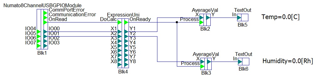
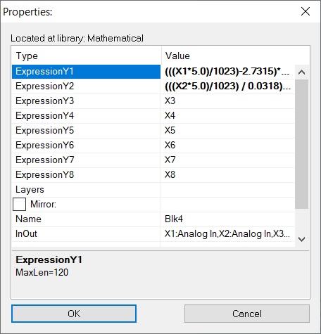
GPIO 0 and GPIO 1 of Numato board are set as Analog inputs and are presented on the right side of the Numato functional block as Analog outputs. With double click over the block ExpressionUni, are set the expressions for temperature and humidity conversions. The both expression are:
(((X1*5.0)/1023)-2.7315)*100.0
(((X2*5.0)/1023)/0.0318)-23.83075
Please note, In parameter from the expressions above, where is explained how to convert ADC value to temperature and humidity is replaced with X1 and X2, because X1 and X2 are names of the inputs of ExpressionUni functional block. The interface with parameters of ExpressionUni is shown below:
The output OnRead of the Numato block is connected with the input DoCalc of ExpressionUni block. This is because, when the Numato block read the data from the analog inputs, its output OnRead becomes for a short time to a high level and this signals the block ExpressionUni to start the calculations. When the calculations are done, the output OnReady of the block ExpressionUni becomes to a high level and signals the next blocks AverageVal to start theirs calculations too.
The blocks after ExpressionUni are AverageVal. They have a parameter QuequeSize, which determines over how many last measurement to be calculated an average value. If the parameter has a small value, the output of the block will float, if the parameter has a large value, the output will be well filtered, but will be slowly. Please change this value and watch the shown temperature and humidity. Suitable values are between 2 and 30.
The calculated average values are shows using Text controls.
When the diagram is run, to change the temperature, just touch the black sensitive element of the temperature sensor. Because the human temperature is higher, the shown temperature at the running AltonaLab diagram will increase. To increase the measured humidity, just blow on the sensor. Because your breath is moist, the sensor will detect more humidity.
Experiment: Measure of temperature using special functional block.
AltonaLab diagram: KIT_Numato8_USB_GPIO_Temp2.nsm
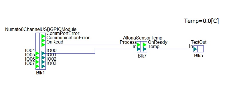
AltonaLab software has a specially developed functional block for temperature measurement: AltonaSensorTemp. The block is used in the diagram below:
Using the parameters of this block, we just have to set that the input of the block gets raw ADC data from 10bit ADC, which works in range 0..5V and with parameter QueueSize to determine the amount of last measurements over which to calculate the average value of the measured signal:
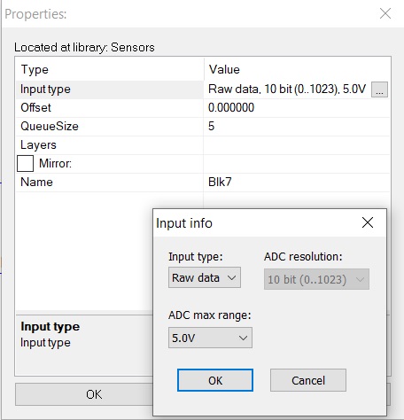
Please note the value of ADC max range is set to 5V, this is because the used Numato board has an ADC working in range 0..5V.
The output OnRead of the Numato block is connected with Process input of AltonaSensorTemp block and when the data is read from Numato block, it signals the next block to start its calculations.
When the diagram is run, to change the temperature, just touch the black sensitive element of the temperature sensor. Because the human temperature is higher, the shown temperature at the running AltonaLab diagram will increase.
Experiment: Measure of temperature and humidity using special functional blocks.
AltonaLab diagram: KIT_Numato8_USB_GPIO_TempHum2.nsm
AltonaLab software has a specially developed functional blocks for temperature and humidity measurement: AltonaSensorTemp and AltonaSensorHumidity. These blocks are used in the diagram below:
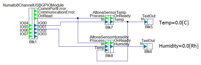
Using the parameters of these two blocks, we just have to set that the input of the blocks gets raw ADC data from 10bit ADC, which works in range 0..5V and with parameter QueueSize to determine the amount of last measurements over which to calculate the average value of the measured signal:
Please note the value of ADC max range is set to 5V, this is because the used Numato board has an ADC working in range 0..5V.
The output OnRead of the Numato block is connected with Process inputs of AltonaSensorTemp and AltonaSensorHumidity blocks and when the data is read from Numato block, it signals the next blocks to start theirs calculations. The block AltonaSensorHumidity has a temperature compensation – input Temp, so if the temperature of the environment is known, it will change slightly the value of the humidity and will increase its accuracy.
When the diagram is run, to change the temperature, just touch the black sensitive element of the temperature sensor. Because the human temperature is higher, the shown temperature at the running AltonaLab diagram will increase. To increase the measured humidity, just blow on the sensor. Because your breath is moist, the sensor will detect more humidity.